
Project Solutions
Wave catcher (4)
Published:2011/7/26 0:54:00 Author:Phyllis From:SeekIC
By Burkhard Kainka
Fixed-frequency
An alternative to a circuit with adjustable tuning is to use a fixed-frequency filter. In the medium-wave band, there is often only one usable reception frequency. Although the relative bandwidth of the input circuit is relatively large, good selectivity is possible thanks to the low frequency. A circuit such as that shown in Figure 6 can thus manage with a fixed inductor. This fixed-frequency filter for 1296 kHz improves reception of the BBC transmitter in the evening hours. It primarily reduces interference from multiples of the oscillator frequency in the short-wave bands. 
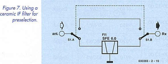
For the 49-m band, a quite simple solution is possible using the type SFE 6 ceramic IF filter, which is used for the sound IF in television sets. Figure 7 shows how to connect the filter to the receiver input so it can be switched in or out as necessary. The specified 3-dB bandwidth of around 100 kHz. which is actually too narrow, is broadened by the low impedances of the aerial and receiver to such an extent that the measured 6-dB comer frequencies are located at 5850 kHz and 6150 kHz. In practice, this filter is primarily useful in the 49-m band when interference occurs from strong transmitters in the 40-m band. At 7 MHz. the filter provides an attenuation of around 40 dB. 
Magnetic-field aerials
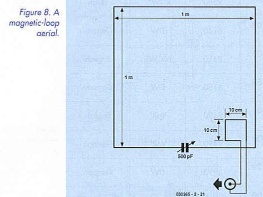
A "longish" wire aerial receives electrical energy from both the electrical and magnetic components of the radio waves. By contrast, short aerials such as rod aerials predominantly receive energy from the electrical component. This results in a higher level of interference, especially inside a building. The coupling between the receiver aerial and electrical equipment or the mains wiring is primarily capacitive. Better results can thus be obtained by receiving the magnetic-field component. In principle, all that is necessary for this is a wire loop or a coil. Commonly used solutions are loop aerials with a few turns of wire or single-winding loops, sometimes called "magnetic loops’. Tuned loops with high Q factors are particularly effective. For instance, you can use a length of copper pipe formed into a circle with a diameter of one meter. However, a broad piece of aluminum foil wound around a cardboard box with suitable dimensions also provides good results.
When connected to a variable capacitor with a maximum capacitance of 500 pF. the loop forms a high-Q resonant circuit and thus delivers a significantly higher aerial voltage than would be expected from an aerial of this size. The receiver should be loosely coupled using a small coupling coil, in order to avoid excessively damping the resonant circuit (see Figure 8). The optimum size and position of the coupling coil is best determined experimentally. Due to the high Q factor of the aerial, an additional preselector is in any case unnecessary. A magnetic loop aerial can also be constructed using normal wire, although this yields a lower Q factor and thus a lower aerial voltage, as well as a larger bandwidth. If it is necessary to make the aerial smaller, two or more turns of insulated wire can be used. 
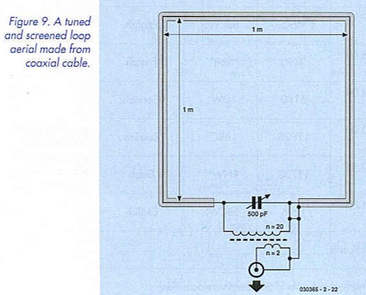
An especially effective solution is an electrically screened loop aerial, which in its simplest form can be made from a length of coaxial cable. Such an aerial can be inconspicuously fitted in a bookshelf, and it provides a relatively good signal to noise ratio. The resonant frequency depends on the size of the loop and the capacitor setting. If the total length of the coaxial cable is four meters, a resonant frequency range extending to below 6 MHz can be obtained with a 500-pF variable capacitor (see Figure 9). The primary inductance of the wideband transformer should be greater than that of the wire loop. Good results can be obtained with 20 turns on a ferrite core or toroidal core. In the interest of obtaining a high Q factor, the tuned circuit should not be too heavily damped. Consequently. the secondary has only two to four turns. The best value for the coupling coil should be determined experimentally. In the medium-wave band, ferrite rod aerials have lone since proven their worth. Like magnetic loops, they are relatively insensitive to electrical interference. Figure 10 shows a ferrite rod aerial followed by an impedance converter. With a 10-mm diameter ferrite rod. the coil requires 70 turns of stranded RF wire (’litz wire") or 0.3-mm enamelled copper wire. Approximately 100 turns are necessary on a thinner rod (8 mm diameter). 

Relatively large resonant voltages arise across the tuned circuit. even with distant transmitters. For example, at the author’s location in Essen. Germany, at peak reception times an open-circuit voltage of 50 mV can be measured across a ferrite rod aerial with a length of 20 cm for the BBC signal at 1296 kHz. At the low-impedance receiver input, this still amounts to 5 mV, which is more than enough steam for our new digital steam radio.
Reprinted Url Of This Article: http://www.seekic.com/blog/project_solutions/2011/07/26/Wave_catcher__(4).html
Print this Page | Comments | Reading(1284)
Article Categories
New published articles
· Imagination works with TSMC to develop FinFET process
Author:Ecco Reading(45477)
· XMOS pushes event-driven MCUs with lower price
Author:Ecco Reading(4141)
· Intel brings upgraded 32-nm SoC for smartphones
Author:Ecco Reading(3864)
· Micron pushes TLC 128-Gbit NAND flash
Author:Ecco Reading(4611)
· Intel will stop supplying desktop motherboards
Author:Ecco Reading(5961)
· Processor market was expected to regain strength in 2013
Author:Ecco Reading(3956)
· It was reported that TSMC sales fall steeply
Author:Ecco Reading(3618)
· Cisco, NXP work with auto wireless startup
Author:Ecco Reading(4282)
· Micron was impacted by manufacturing glitch
Author:Ecco Reading(4647)
· China can make 22-nm transistor by themselves
Author:Ecco Reading(4485)
· Chip market rebound is coming, according to survey
Author:Ecco Reading(4386)
· Sony, Toshiba will spend more on chips, iSuppli reports
Author:Ecco Reading(3953)
· Qualcomm becomes the 13th company to join NFC Forum board
Author:Ecco Reading(6795)
· TSMC increases building work for FinFET fab
Author:Ecco Reading(4467)
· TI plans to cut 1,700 jobs in OMAP shift
Author:Ecco Reading(5327)