
Project Solutions
High-End-Preamp (7)
Published:2011/7/25 1:45:00 Author:Amy From:SeekIC
By Benjamin Hinrichs
Testing, testing, testing... and into the box
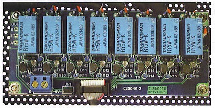
Before inserting the microcontroller and the PGA2311 into their sockets and connecting the display, you should painstakingly check all the boards for incorrectly fitted components, dubious solder joints and solder bridges. The first test should be performed with the boards outside of the enclosure. To hold the boards securely in place for testing, screw them to the workbench using standoffs under each of the boards.
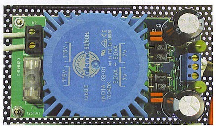
First connect the power supply boards and check the voltages at their outputs. Due to the high open-circuit voltage and the combination of rectification and filtering, the measured voltage will naturally be somewhat higher than the 7 V specified for the transformer.
Next, connect all of the boards together and switch on the power. Nothing will happen, but the following voltages should be present at the appropriate IC pins and the display module connector:
+5V: K3-2, IC1-12, IC1-35, IC2-4, IC2-12
-5V: IC2-13
If everything is OK, wait a few minutes to allow the capacitors to discharge, and then insert the ICs and connect the display.
The display, the microcontroller and the volume control IC are highly sensitive to static electricity. As all of these components are not exactly inexpensive, you should work at a suitably earthed workstation.
Figure 7 gives a deep insight into the laboratory prototype of the digitally controlled high-end preamp. The mains filter was fitted because it was ’already on hand’, but it is fully adequate. The power supply boards and the main board are separated as far as possible. Nevertheless, the FFT analysis (see Part 1) shows that induced 50-Hz noise is responsible for the majority of the distortion. If you want to improve matters and are not afraid of a bit of effort, you can fit the sensitive audio portion into a suitable tin-plate enclosure. 
At the rear, besides the mains input socket there are two sets of eight audio inputs and two audio outputs, all using isolated gold-plated Cinch sockets. After the ’official’ completion of the device in the Elektor Electronics lab, further tinkering revealed that small RC networks on the inputs suppress induced RF noise on the cables, and that a lOO-Q series resistor in each of the output lines assures the stability of the PGA2311. As shown in Figure 8. These components should be soldered directly to the Cinch sockets using the shortest possible leads, or even fitted in the connecting cable, in order to maintain the highest possible degree of screening. 
In contrast to the audio connections, which employ high-quality twin screened cable, the keypad (which does not have a circuit board) and the front-panel LED are connected using simple flat cable. This allows a relatively large amount of freedom in the layout of the front panel. For example, the volume buttons can be arranged in a diamond pattern (if sufficient room is available). You can spare yourself the trouble of looking for a distributor for the attractive metal buttons used for the prototype-they were personally turned by the author.
The bright red cable between the main circuit board and the LC display came from a computer shop. But be careful: many of the cables available in such shops have crossed lead pairs. In case of doubt, a ’normal’ flat cable is also perfectly satisfactory.
Reprinted Url Of This Article: http://www.seekic.com/blog/project_solutions/2011/07/25/High_End_Preamp_(7).html
Print this Page | Comments | Reading(2076)
Article Categories
New published articles
· Imagination works with TSMC to develop FinFET process
Author:Ecco Reading(33527)
· XMOS pushes event-driven MCUs with lower price
Author:Ecco Reading(3534)
· Intel brings upgraded 32-nm SoC for smartphones
Author:Ecco Reading(3250)
· Micron pushes TLC 128-Gbit NAND flash
Author:Ecco Reading(3816)
· Intel will stop supplying desktop motherboards
Author:Ecco Reading(5341)
· Processor market was expected to regain strength in 2013
Author:Ecco Reading(3318)
· It was reported that TSMC sales fall steeply
Author:Ecco Reading(3474)
· Cisco, NXP work with auto wireless startup
Author:Ecco Reading(3620)
· Micron was impacted by manufacturing glitch
Author:Ecco Reading(4017)
· China can make 22-nm transistor by themselves
Author:Ecco Reading(3820)
· Chip market rebound is coming, according to survey
Author:Ecco Reading(3761)
· Sony, Toshiba will spend more on chips, iSuppli reports
Author:Ecco Reading(3790)
· Qualcomm becomes the 13th company to join NFC Forum board
Author:Ecco Reading(6105)
· TSMC increases building work for FinFET fab
Author:Ecco Reading(3778)
· TI plans to cut 1,700 jobs in OMAP shift
Author:Ecco Reading(4587)