
Project Solutions
High-End-Preamp (5)
Published:2011/7/24 22:37:00 Author:Amy From:SeekIC
By Benjamin Hinrichs
Channel switching
The input channels are switched on the relay board. The circuit shown in Figure 3 allows two different wiring options. 
With the traditional option, all eight inputs from the Cinch sockets are used, with a single output to the main circuit board. This requires JP2 and JP3 to be fitted. Each relay is then responsible for one stereo channel. If standard twin screened audio cable is used, one channel is connected to A and the other to B, and the screen braid is soldered to the bottom of the circuit board. Ground isolation, which may be desired to improve channel separation or avoid interconnecting the grounds of different items of equipment connected to the preamplifier, can be achieved by switching not only the signal lines, but also the associated ground potentials. In this case, for each channel the ’live’ lead is soldered to A and the ground lead is soldered to B. In addition, jumpers JP2 and JP3 are left open. In this mode, each pair of relays (RE1 & RE5, RE2 & RE6, RE3 & RE7, and RE4 & RE8) belongs to a single signal source. This yields four stereo inputs and two sets of outputs (OUT1A & OUT1B and OUT2A & OUT2B). Here again A corresponds to the ’live’ lead and B to ground. The only other thing you have to do is to change the Input Type option in the Set-up menu to ’Double’.
In order to handle balanced signals, we simply switch two relays simultaneously. In this mode, you also have to add a second, parallel volume control and then connect the balanced signals to one of the input channels (such as Left In) on both volume controls. This works well-quite well, in fact.
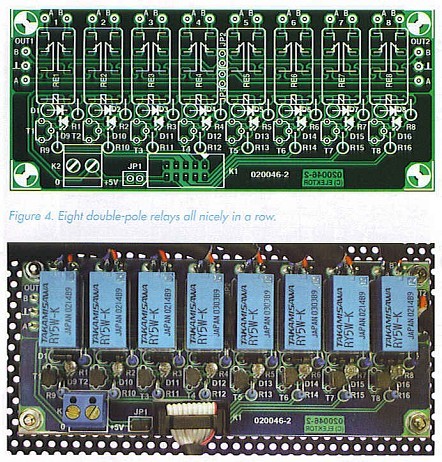
Fujitsu (formerly Takamisawa) type RY-5W-K relays are used here. Naturally, other pin-compatible types could also be used, but the specified line has excellent characteristics and is available for less than 2 euros (approx. £1.40), for example from Conrad Electronic (www.conrad.de). This is a plastic-encapsulated relay, which prevents any dust from accumulating inside. The contacts are made from a silver-palladium alloy with supplementary gold plating.
Power for the relay board is taken from the main circuit board via connector Kl (which requires jumper JP1 to be fitted). If you wish to treat the channel switching board to its own power supply or you want to use this board in a different project, you can also connect a 5-V supply to the K2 terminals.
In order to avoid overloading the microcontroller outputs, transistors with base resistors are used as relay drivers. Diodes D1-D8 act as free-wheeling diodes, while LEDs D9-D16 provide a visual indication of the relay states. The LEDs do not necessarily have to be fitted to the circuit board (Figure 4); they can of course be fitted to the front panel instead if you want to do without the display, or they can simply be omitted (along with then-series resistors). 
JP1 can be implemented as a jumper, but JP2 and JP3 should be implemented as wire bridges. Otherwise there’s not anything particularly remarkable about populating the circuit board, particularly if you use the components specified in the components list and everything fits perfectly.
Reprinted Url Of This Article: http://www.seekic.com/blog/project_solutions/2011/07/24/High_End_Preamp_(5).html
Print this Page | Comments | Reading(3210)
Article Categories
New published articles
· Imagination works with TSMC to develop FinFET process
Author:Ecco Reading(33527)
· XMOS pushes event-driven MCUs with lower price
Author:Ecco Reading(3534)
· Intel brings upgraded 32-nm SoC for smartphones
Author:Ecco Reading(3250)
· Micron pushes TLC 128-Gbit NAND flash
Author:Ecco Reading(3816)
· Intel will stop supplying desktop motherboards
Author:Ecco Reading(5341)
· Processor market was expected to regain strength in 2013
Author:Ecco Reading(3318)
· It was reported that TSMC sales fall steeply
Author:Ecco Reading(3474)
· Cisco, NXP work with auto wireless startup
Author:Ecco Reading(3620)
· Micron was impacted by manufacturing glitch
Author:Ecco Reading(4017)
· China can make 22-nm transistor by themselves
Author:Ecco Reading(3820)
· Chip market rebound is coming, according to survey
Author:Ecco Reading(3761)
· Sony, Toshiba will spend more on chips, iSuppli reports
Author:Ecco Reading(3790)
· Qualcomm becomes the 13th company to join NFC Forum board
Author:Ecco Reading(6105)
· TSMC increases building work for FinFET fab
Author:Ecco Reading(3778)
· TI plans to cut 1,700 jobs in OMAP shift
Author:Ecco Reading(4587)