
Project Solutions
High-End-Preamp (4)
Published:2011/7/24 21:30:00 Author:Amy From:SeekIC
By Benjamin Hinrichs
The multitude of options for constructing your ’personalised’ high-end preamplifier mean that you must read this second part of the article before you order the parts and take up your soldering iron. This is because your requirements determine how many circuit boards of which type you will need, as well as which components you will need. You can connect several volume controls in parallel as illustrated in Figure 1, in order to adjust more than two channels at the same time. If you do this, you must interconnect the CS, Mute, SCLK, +5 V and Ground terminals of the circuit boards. SADATO from the first circuit board is connected to SDATI of the next circuit board, and so on. This causes the volume level setting to be communicated to all of the circuit boards. You can choose from traditional audio signal switching, switching the ground leads together with the signal leads, or switching balanced signals. If you know how, you can also give the microcontroller additional functionality or modify the details in the software, such as the designations shown on the display. 
Populating the board
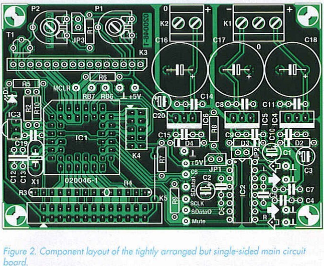
What we need now are a few instructions for populating the main preamplifier board. This is because the circuit board shown in Figure 2 is quite compact. The closely spaced, narrow tracks are not particularly forgiving of mistakes, so the components should be fitted properly the first time, and solder splashes and overheated joints should be assiduously avoided. On the main circuit board, only JP1 and JP3 can be implemented as jumpers. JP2 (directly underneath IC2) is a wire bridge. There is another wire bridge at the inner edge of K5, which should be fitted immediately: done is done! 
Now you should consider whether the programming and/or paralleling connections are necessary. If you arrive at a positive conclusion after studying the two text boxes, then you must fit the associated connectors (refer to the components list) and the solder pins for the audio signals. Despite all the claims to the contrary, it certainly makes sense to fit the solder pins before the other components. Generally speaking, they need a bit of coaxing, and sometimes they can only be pressed into the holes using (brute) force. Besides this, a 1.3-mm diameter silver-plated steel pin requites a considerable amount of heat to achieve a reliable bond with the solder. And if you find a solder pin standing at an angle to the board, you can start all over again. This can be the kiss of death for small, sensitive components that have already been fitted in the immediate vicinity.
If you use a decent stuffing frame, it doesn’t matter very much if the low-profile components (resistors, capacitors, and diodes) are only fitted afterwards. As always, proper polarisation is important for some of the components. Besides the diodes and small electrolytic capacitors, this also includes the resistor arrays and the PLCC socket, which is bevelled on one corner. This marking must match the component overlay on the circuit board. Now it the right time to not fit LED Dl if you want to use it as a pilot light on the front panel. This LED, along with IR receiver IC3, should only be soldered in place after the circuit board has been securely fitted in the enclosure and the two components have been fastened in holes drilled in the front panel. If your enclosure layout does not permit the circuit board to be placed directly behind the front panel and you thus must fit the IR receiver off the board, a screened connection cable is mandatory. , The fixed voltage regulators IC4-IC6, which should be soldered in place after pin headers K3-K5 and the high-quality DIL socket for the PGA2311 have been fitted, do not require heat sinks. The soldering work is completed with the fitting of the three large electrolytic capacitors and the two circuit-board terminal strips (Kl and K2). If you wish to control several volume control boards in parallel, fully populate one main circuit board and fit only the portion with the PGA2311 (including the peripheral circuitry and the voltage regulator circuitry) on the other boards.
The system has been tested using a single controller board and two parallel circuit boards. All of the necessary connection points are located in a row on the circuit board.
Reprinted Url Of This Article: http://www.seekic.com/blog/project_solutions/2011/07/24/High_End_Preamp_(4).html
Print this Page | Comments | Reading(879)
Article Categories
New published articles
· Imagination works with TSMC to develop FinFET process
Author:Ecco Reading(33527)
· XMOS pushes event-driven MCUs with lower price
Author:Ecco Reading(3534)
· Intel brings upgraded 32-nm SoC for smartphones
Author:Ecco Reading(3250)
· Micron pushes TLC 128-Gbit NAND flash
Author:Ecco Reading(3816)
· Intel will stop supplying desktop motherboards
Author:Ecco Reading(5341)
· Processor market was expected to regain strength in 2013
Author:Ecco Reading(3318)
· It was reported that TSMC sales fall steeply
Author:Ecco Reading(3474)
· Cisco, NXP work with auto wireless startup
Author:Ecco Reading(3620)
· Micron was impacted by manufacturing glitch
Author:Ecco Reading(4017)
· China can make 22-nm transistor by themselves
Author:Ecco Reading(3820)
· Chip market rebound is coming, according to survey
Author:Ecco Reading(3761)
· Sony, Toshiba will spend more on chips, iSuppli reports
Author:Ecco Reading(3790)
· Qualcomm becomes the 13th company to join NFC Forum board
Author:Ecco Reading(6105)
· TSMC increases building work for FinFET fab
Author:Ecco Reading(3778)
· TI plans to cut 1,700 jobs in OMAP shift
Author:Ecco Reading(4587)