
Project Solutions
A dipole antenna for 4 meters (1)
Published:2011/7/24 22:12:00 Author:Phyllis From:SeekIC
No receiver is complete without a matching antenna. Commercial offerings for the 4-m band being few and far between (or scrapped by PMR fleet owners), we decided to present a design for a low-budget get-u-going dipole. Not sophisticated, want a directional antenna? Then try the links at the end of this article. Too difficult? It doesn’t get much simpler than this, so give this antenna design a try and you’ll be pleasantly surprised. The antenna is great for initial experiments even when installed on your attic.
Our ingredients and tools are:
* a length of 50 O. RG213 or RGB coax cable (10.3 mm outside diameter)
* a piece of copper pipe, 15 mm outside diameter, length 965 mm
* two aluminium rods, 6 mm diameter, length 1 m
* two cable eyelets
* a round T-junction box for electrical conduit, 20 mm openings
* some not too thin wire
* a powerful soldering iron (> 50 watts)
* nylon or plastic bushes, 20 mm diameter
* permission from the missus
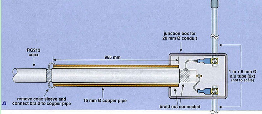
The drawing in Figure A is intended as a guide to constructing the antenna. The copper pipe acts as a balun (balanced to unbalanced transformer), not only matching the asymmetrical coax cable to the symmetrical dipole, but also stepping down the dipole impedance of about 72 D to the cable impedance of 50 il. RF buffs will like to refer to it as a bazooka or sleeve balun. Unless you have electrical connection materials to fit to the rod ends (like a 60-A electrical ’chocolate block’ terminal strip), simply flatten and drill the ends of the aluminium rods to allow screws to be used for the connection with the cable eyelets. For extra rigidity, the rods are fed through bushes (drilled to accept them) where they enter the junction box, and the box itself may be filled with potting compound or hard setting silicone sealant. The other ends of the alu rods should be deburred, rounded off and sealed to prevent moisture ingress. 
If the antenna is to be used out of doors, the junction of the copper pipe and the coax braid should be protected as well. This may be achieved by inserting the balun assembly in a length of 20-mm dia conduit and filling the lot with silicone sealant. All soldering to the coax cable should be done as quickly as possible to prevent deformation of the PTFE (Teflon) core and consequently creating ’impedance humps’.
Variations on the theme are possible, but be careful if you lack experience. You may, for instance, decide to use much thinner material for the dipole arms (for instance, lengths of welding rod), thinking it will make no difference as it is only the length that counts. Wrong, because your antenna will lose much of its broadband response and will present an acceptable VSWR at about 75 MHz ± 2 MHz only. A larger rod diameter increases the bandwidth so the antenna can be used for the entire VHF-Low band (68-88 MHz). That is why base antennas use for PMR services in the VHF bands are so thick!
On the rack!
While tidying up the design of the VHF-Low Explorer for publication in this issue, an opportunity arose to have our little receiver tested on a high-end instrument called the Rohde & Schwarz CMS 54 Radio Communications Service Monitor. This instrument (pictured here) can perform automated measurements across the frequency range Q.A MHz to 1 GHz v/hich is not normally within the capacity of the RF test equipment available in the Elektor Electronics design laboratory. The offer came from Mr. Ed Warnier PAlEW who is totally conversant with this piece of kit, handling and operating it as if he were driving his car to the supermarket. Not only the test results obtained from the receiver are worth telling you about, but also the basics of some of the specific tests the instrument can perform, as they may be unknown to many readers entering the radio hobby. 
A few facts had to be established first. Our receiver is designed for narrowband FM (NBFM) reception between 68 MHz and 88 MHz, these values marking what is generally referred to as the VHF-Low communications band. As the receiver is of specific interest to radio amateurs, it was decided to tune it to 70.250 MHz being the centre of the 4-metre band as defined by the IARU. The receiver being VFO tuned and lacking a frequency readout, reverse thinking quickly lead to the CMS 54 being set to 70.250 MHz and cheerfully tuning the receiver until the test signal v/as audible.
Hooray, it works!
Reprinted Url Of This Article: http://www.seekic.com/blog/project_solutions/2011/07/24/A_dipole_antenna_for_4_meters__(1).html
Print this Page | Comments | Reading(4875)
Article Categories
New published articles
· Imagination works with TSMC to develop FinFET process
Author:Ecco Reading(33527)
· XMOS pushes event-driven MCUs with lower price
Author:Ecco Reading(3534)
· Intel brings upgraded 32-nm SoC for smartphones
Author:Ecco Reading(3250)
· Micron pushes TLC 128-Gbit NAND flash
Author:Ecco Reading(3816)
· Intel will stop supplying desktop motherboards
Author:Ecco Reading(5341)
· Processor market was expected to regain strength in 2013
Author:Ecco Reading(3318)
· It was reported that TSMC sales fall steeply
Author:Ecco Reading(3474)
· Cisco, NXP work with auto wireless startup
Author:Ecco Reading(3620)
· Micron was impacted by manufacturing glitch
Author:Ecco Reading(4017)
· China can make 22-nm transistor by themselves
Author:Ecco Reading(3820)
· Chip market rebound is coming, according to survey
Author:Ecco Reading(3761)
· Sony, Toshiba will spend more on chips, iSuppli reports
Author:Ecco Reading(3790)
· Qualcomm becomes the 13th company to join NFC Forum board
Author:Ecco Reading(6105)
· TSMC increases building work for FinFET fab
Author:Ecco Reading(3778)
· TI plans to cut 1,700 jobs in OMAP shift
Author:Ecco Reading(4587)